Friday, January 22, 2010

Super Update!

Like I said via twitter, sorry for not posting last night as I promised but I'm making it up to you with lots of pictures of the progress we have been making.

- Wes

I know you've been seeing a lot of the top hats but I promise it's Ben's last one.

Ben so excited to be wrapping up his work on the CNC mill

The beast that has been working non stop lately

With the frame in from Cartesian Tube Profiling, Ryan Zeiset went right to work assembling the frame so that it will be ready to be welding this weekend

Front view of the setup

Sideview

One of the many joint to be welded


A view from the inside of the frame

The intricacies of the frame

Last shot of the frame

Kyle's intake mold is ready for a carbon fiber sleeve

A big thanks to Wayne for making us some new welding tables and offering us welding classes!


The dyno

From the other (more confusing looking) side

Saturday, January 16, 2010

New Website

Jackets Racing has upgraded from a blog to a real website!

Go check it out: http://fsae.cedarville.edu/

Friday, January 15, 2010

Brakes and Top Hats

January 15, 2010

Ben Beall made some great progress yesterday on the top hats for the braking system. He was up late into the night on the CNC.


Starting the top hat


Close up of the top hat


Ben Beall showing off his masterpieces


Close up of two of the four top hats

Thursday, January 14, 2010

Frame and Carbon Fiber Rims

The frame is in and Jon's making good progress on the carbon fiber rims.

 The New Frame Cut by Cartesian Tube Profiling

Friday, January 8, 2010

Twitter and Frame

The Jackets Racing team is now on twitter! Check us out at http://twitter.com/jacketsracing

We also want everyone to know that our frame back from Cartesian Tube Profiling (www.cartesiantube.com) and is ready to be assembled! The manufacturing phase is underway.

- Wes Muntz

Tuesday, December 15, 2009

Design Phase Completed

With a lot of hard work and determination the team has completed the assembly of the car in Solidworks and is entering into the manufacturing stage. There has been a lot of blood, sweat and tears put into the project so far, well, maybe not any tears. We are continuing to work hard even after classes have ended and finals are finished. Work will continue over most of the break to achieve our goal of having the car constructed and running by March 1. We found the design phase to be challenging and rewarding, we expect the manufacturing phase to be no different.


Tuesday, November 17, 2009

Drivetrain Team Update - Knuckles

The drivetrain team set out with many challenges and goals this year. The designing of the knuckles were done from scratch due to re-designing of the suspension system. This was a challenging but fun task. It required working closely with the suspension, brake and hub design team members. The design went through many iterations until the final design was reached. Finite Element Analysis was performed on the knuckles using Algor. The factor of safety of the front knuckle is 2.6 and weighs approximately 2.4 pounds.


Front Knuckle Design


Rear Knuckle Design


Front Knuckle, Hub, and Brake Assembly

- Brian Blocher

Monday, November 16, 2009

Brakes

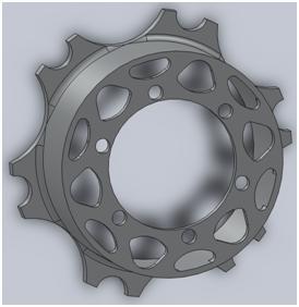
The design of the rotors was not a quick or easy job. There were many factors that had to be looked into for the design such as the weight of the car that the brakes needed to stop, the size of the wheels that the rotors were to be packaged in, the manufacturability of the assembly, the size of the calipers, and the hydraulic pressure in the lines required to lock all the wheels just to name a few. We went through multiple iterartions to finalize the design we have now. The final design includes four outboard disc brakes and incorporates the use of a top hat with a floating rotor. They are shown in the figures below.

- Ben Beall


Front Rotor


Top Hat

The rotors float on the top hat through the use of the floating rotor buttons. These buttons are wider than the thickness of the rotor and top hat, so the rotors can shift a few hundredths of an inch on the top hat in order to stay centered in the calipers. Once we designed everything that we wanted for the disc brakes, we put them together in an assembly in SolidWorks.


Rear Brake Assembly

Once we had created an assembly, we were able to put the model into ALGOR to simulate the stresses the rotor would see. This allowed us find the factor of safety for the disc brake and make design changes based off how big or small the safety factor was.


Model of Rear Floating Rotor Assembly in ALGOR

Wednesday, October 28, 2009

Engine Team Update

Engine team has finished its design of the intake and exhaust systems. The team utilized the WAVE software package to design the systems. Using knowledge from the classroom, a SAE video seminar, and lots of advice and mentoring from Cedarville grads, the team was able to accurately analyze the performance of the engine with different intake runner and exhaust header lengths. The results were encouraging! Based upon the model, the motor will make good, smooth, and sustained torque in the mid to high engine speed range.

One current project is modifying the existing oil pan. A new base will be machined from aluminum sheet metal and welded to the stock oil pan, thereby shortening the height of the pan. The engine was picked up and dropped off at the shop last week, and the new Haltech Sport 1000 ECU was just delivered today. The team has done some minor prep work on the engine and is excited to get it running on the dynamometer for tuning. Check back in a few weeks for pictures of the custom-made intake, exhaust, and radiator!

- Scott Bardakjy


WAVE model of 2008 Suzuki GSX-R600 engine.


Comparison of torque figures vs. previous cars.


Comparison of power numbers vs. previous cars.


Removing stock exhaust system.


Cutting out pieces for the oil pan on the band saw.

Tuesday, October 6, 2009

Suspension Points

The suspension team just met a BIG deadline Monday, nailing down the A-arm attachment points to the chassis and uprights. This was the first big bottleneck of our project. The drive train team can now design the uprights around the upright attachment points and the frame and body team can design around the chassis attachment points. We used the commercial supension design software package OptimumK to design the A-arm geometry. The program allows a suspension system to be easily designed and then analyzed by subjecting it to roll, pitch, heave, and steering.  We're pretty excited about the momentum we have so far as a team, and hope that it continues to build!

- Andrew Biehl


A-arm geometry modeled in OptimumK